High-Speed Digital Connector Design
In previous installments of this series, we described the importance of impedance. However, we haven’t discussed how to determine the impedance of the path, or the variables that impact impedance. That is the focus of this installment.
Unfortunately, impedance is very difficult to calculate. In fact, it is nearly impossible to calculate without a high-powered electromagnetic field solver.
Due to this complexity, it is often helpful to simply understand the implications of specific design changes on impedance. This can help us make the necessary design changes to increase or decrease the impedance of our current design.
The impedance of any path is determined by the cross-sectional geometry at any point in the path. For any path where the cross-section changes, the impedance will have some variation.
In most cable / connector assemblies, this occurs in the connector: It is relatively easy to keep the cross-section of a shielded, twisted pair cable constant.
However, it is very difficult, if not impossible, to keep the cross-section constant as the path transitions from the cable, to pins, and sometimes on to a circuit board.
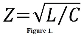
Impedance (Z) is proportional to inductance (L) and inversely proportional to capacitance (C) (see equation in Figure 1). In order to understand this equation, it is necessary to have a general understanding of inductance and capacitance.
Inductance is the ability to store magnetic charge, and it is determined by the size of the circuit loop. The size of the current loop is determined by the size of the conductors (length / width) as well as the distance between the conductors. Inductance increases as the size of the loop increases, and decreases as the width of the loop increases.
Capacitance is the ability to store electric charge. Capacitance increases as the size of the conductors increases, and decreases as spacing between conductors increases. Capacitance is also proportional to the dielectric constant (eR), a material constant of the insulating plastic that is typically provided on the datasheet of the insulator.
Figure 2 describes how several design parameters impact impedance. As the distance between conductors increases, the inductance increases and the capacitance decreases.
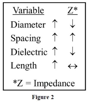
Both of these factors will cause the impedance to increase. For cables, the insulator diameter determines the spacing between wires, so impedance increases as this diameter increases. In connectors, the impedance increases as the spacing between the pins increases.
As the diameter of the conductors increases, the inductance decreases and the capacitance increases. These both cause the impedance to decrease. The dielectric constant of the insulating material also impacts impedance.
However, since dielectric constant only affects capacitance, not inductance, the impact of dielectric constant on impedance is less profound than diameter and spacing.
Impedance has an inverse relationship with dielectric constant: as the dielectric constant of the insulating material increases, impedance decreases.
Finally, impedance has no relationship to length. Since length increases inductance and capacitance with the same proportion, length has no impact on impedance. This is why impedance is a function of cross-sectional geometry and can be determined at any point along a path.
Impedance is an important parameter for all high-speed designs. It’s critical that designs are optimised to provide a matched impedance throughout the entire path.
This installment was intended to help designers understand how different design decisions may impact the impedance.